The Basics
Spring applied brakes, also sometimes known as normally on brakes and failsafe brakes are most commonly encountered as electromechanical devices with DC current release actuation. When the supply current is interrupted the brake engages and remains on. This suits them to emergency stop and holding duties. They are used in high numbers in applications such as cranes, hoists, industrial trucks, and vehicles for the disabled, wind turbines, gates, escalators and brake motors.
Spring applied brake designs are well-developed with high reliability and a stable friction torque that suits both dynamic braking and static holding. Standard designs with modular options are readily available with body diameters 37 to 390mm and corresponding torques from 0.1 to 2400Nm.
How they work
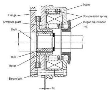
Although there are a number of variants on the market, the majority of spring applied brakes are single disc designs with a DC coil for release. A rotating disc, usually referred to as the rotor, is connected to the machine shaft using a splined hub that allows axial movement of the rotor. In normal operation the axial movement of the rotor is 0.1 to 1.5 mm and the splines are sized to transmit the brake torque with low stress and wear. The rotor has a surface of friction material on both sides.
An assembly of the coil and helical springs, known as the stator, is assembled over the rotor by 3 to 6 fixing bolts. This clamps the rotor between a floating plate in the stator, the armature plate, and the machine surface. Sometimes an intermediate mounting plate is used.
Within the stator assembly the armature plate is mechanically pre-set so it can be pulled back axially by magnetic flux from the DC coil. The movement of the armature plate is thus through the air gap of the brake (Slü) freeing the rotor when the coil is energised. When the supply is interrupted, a number of helical springs push the armature back to clamp the rotor. So in the absence of electrical power, torque is generated between the rotor and a combination of armature plate and mounting surfaces. When the coil is energised the armature plate moves back compressing the springs and the rotor is free to rotate.
Ultimately, these brakes are not truly failsafe although they are highly reliable as witnessed by B1Od figures of 3 to 6 million hours. However, lack of maintenance, overload or long-life fatigue can cause unpredictable failures. In safety-sensitive applications, spring loaded brakes should be selected with suitable service factors, usually 2.0 or higher.
The majority of brakes are powered by DC current connected to a single toroidal coil. DC is preferred to AC because it does not suffer from current inrush problems or from noise. However switching of DC coils is slower and precautions are required for use with falling loads.